ST4 DIY – Mic board
The mic board contains a microphone, line input and an ADC to digitize both. The digitized signal is sent towards the Micro Controller Unit (MCU) on the Arduino DUE.
The parts list is as follows:
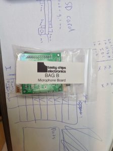
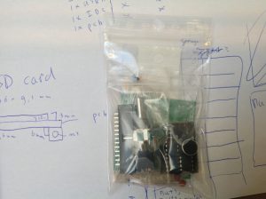
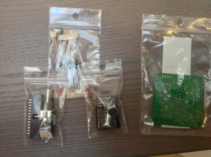
The following pictures show how your mic board kit bag (B) should look..


Start by soldering the lowest parts. These are the resistors. There are many values as is common in analog designs. Just group by value (for instance all 1k’s, then all 10k’s, then all 22k’s, etc) until all of them are soldered. See the pictures below:
Next up are the ceramic caps. The 100 nF ceramics’s are used to bypass the IC’s and can be found close to them. The 1 nF’s are for low-pass filtering and are less close:

The IC sockets are next. Mind the orientation! Insert them correctly, bend the 2 of the outer most pins to lock them in, and then solder all the pins.

The Elco’s are next. These are polarized! So please mind the orientation or risk these things getting fried!
Solder the mic at the height as seen in the photo:
Then the PJ301 line input socket:
Then the pot. This should be _without_ detent!

Solder the IDC26 socket with the cap towards the inside of the board.

Populate the IC’s. IC1 = the ADC, IC2 and IC8 are precision opamps (LT1013). As always, take care of the orientation. Reversal will lead to dead IC’s!
All done!


