ST4 DIY – Mod board
The mod board controls LFO modulation parameters and envelopes. The left side of the board: balance pots (with detent) are used to directly control LFO influence on a matrix of 4 channels and 3 functional units (VCO, VCF, VCA). The right side: sliders are used to control envelope parameter in classic ADSR fashion.
Just to avoid a misunderstanding: the board does not have its own modulators, envelope generators, etc. This is done inside the microcontroller unit (MCU) onboard the Arduino DUE board. The MCU then uses other off-board hardware to generate the CV’s to control the analog VCF’s and VCA’s.
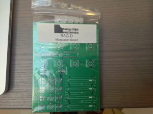
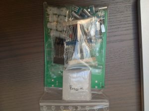
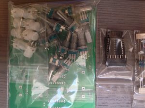
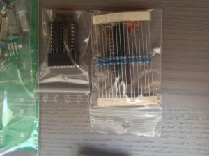
Your mod board kit should look like the following photos:


Start with the lowest components. In this case that’s the 74HC595 and the 74HC165 (SOIC16 packages). Take care of the orientation.
WARNING: if you have the revision g PCB, please note that the the little “gap” on the 74HC595D (IC3) is on the lower side! Unfortunately this is easily confused with the “D” in 74HC595D!! So, beware. Pin 1 should be on the lower side of the PCB!!

Now the resistors. Group these by value, so start with the 10k’s, then move on to 470’s.
The IC sockets. Next up are the IC sockets. Beware that these are polarized! Use the correct orientation and align them with the silkscreen! For easier soldering just bend the socket pins so that the sockets are now effectively stuck to the PCB and then just flip it and solder all pins in one go.
Now the caps. These are all 100 nF and go next to the IC’s.
Now the LED buttons. Take care of the orientation. The flat side should be to the right. This is also indicated on the silk screen.
Best is to now solder the IDC26 socket on the bottom. If you do it later it’ll be harder to solder because you have to reach between all the pots.. Just make care the orientation is correct.
The sliders. There’s only one way to fit them, but you may have to slightly bend the pins and exert some force to push them down.
Push the 4051 IC’s into their sockets.. mind the orientation.
Finally, the potentiometers. Take care that these are WITH DETENT, i.e. they should “click” when they are in center position. Just make em snap and solder.
All done!


