ST4 DIY – VV Board
The VV board, or VCF/VCA controls board, does just that. It allows the musician to control VCF and VCA parameters. All potentiometer signals are multiplexed and sent to the MCU on the Arduino Due. Button presses are also transmitted to the Due. LED’s are driven by the 74HC595 shift register and controlled by the MCU. In other words: this board has no VCA or VCF on board or any analog peripherals. It is merely a front-end to the entire digital/analog signal path.
The Bill Of Materials:
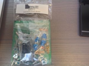
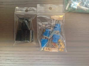
The kit bag for your VCF/VCA controls board should look like the following photos:

Start with the SOIC IC, mind the orientation. Then group the resistors by value and solder each group…
Now solder the bypass caps (100 nF ceramic).
Solder the pot filter caps (1uF ceramic).
Solder the IC sockets. Mind the orientation. Insert them and bend 2 of the pins per socket to the inside to fasten them. Then just solder pins one by one.
Solder the buttons. Mind the orientation: flat side should be to the right. See photo:
Now insert the LEDs together with the spacers. Mind the orientation and follow the example below (click to view full resolution):

The connector goes on the underside of the PCB. Mind (orientation of) the gap! See the photo.
Now do the pots. Note that the rightmost column is for panning, so WITH DETENT, and the rest is all without. Snap and solder.
All done!


