ST4 DIY – VCF board
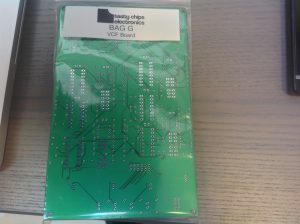
VCF board (revision d):
This is perhaps the most labor intensive of them all. 4 channel multi-mode VCF with voltage controlled resonance! It takes input in the form of 4 voice signals, 4 cutoff control voltages and 4 resonance voltages. The control voltages are 0..5V. You can provide external CV’s on the connector pins if you like. TODO: connector layout. But the CV’s do require biasing.. It outputs 4 signals to the VCA board..
The VCF board is not the trickiest, but it will take you a good 6 hours, most likely. There’s just a wealth of resistors in many values, and a good few DIP sockets to boot.
The Bill Of materials:
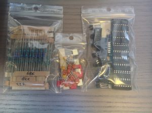
Your VCF kit should look like the following photos:


Resistors, loads of them. You know the drill. Group by value and go.
SMD IC’s (analog muxes):
Ceramic bypass caps, and IC sockets. Take care of the IC socket orientation. Bypass caps are all 100 nF and close to the IC’s!
All the other caps. The red caps are 220 pF polyester box caps, the white ones are 100 nF box caps. The ones near the output muxes are 1 nF ceramic (for decoupling). There are also some additional ceramics for bypassing.
IDC connectors: TODO: another pic with IDC’s! The stripes on the silkscreen indicate where connector gaps should be.
Transistors. TODO: indicate with red the PNP and NPN groups!
Populate the IC sockets (once again, mind the orientation) and.. all done!


